Diferencia entre revisiones de «Memoria de practicas: Circuito RC en Alterna»
De Portfolio Academico
| Línea 7: | Línea 7: | ||
La impedancia total del circuito viene dada por la impedancia de la resistencia y la del condensador. | La impedancia total del circuito viene dada por la impedancia de la resistencia y la del condensador. | ||
<math>Z_T=Z_R+Z_C</math><br><math>Z_R=3.3k\Omega \ _{0^\circ}</math><br><math>Z_C=\frac {1}{2\pi f C}_{-90^\circ}=\frac {1}{2\pi\cdot 50 \cdot 1\cdot10^{-6}}_{-90^\circ}=3183,09\Omega \ _{-90^\circ}</math><br><math>Z_T=Z_R+Z_C= 3300_{0^\circ}+3183.09_{-90^\circ} = \sqrt{3300^2+3183.09^2}_{tan^{-1} \frac{-3183.09}{3300}} </math> | <math>Z_T=Z_R+Z_C</math><br><math>Z_R=3.3k\Omega \ _{0^\circ}</math><br><math>Z_C=\frac {1}{2\pi f C}_{-90^\circ}=\frac {1}{2\pi\cdot 50 \cdot 1\cdot10^{-6}}_{-90^\circ}=3183,09\Omega \ _{-90^\circ}</math><br><math>Z_T=Z_R+Z_C= 3300_{0^\circ}+3183.09_{-90^\circ} = \sqrt{3300^2+3183.09^2}_{tan^{-1} \frac{-3183.09}{3300}} = 4584.98_{-43.96^\circ}\Omega</math> | ||
Revisión del 15:17 25 oct 2013
Cálculos previos
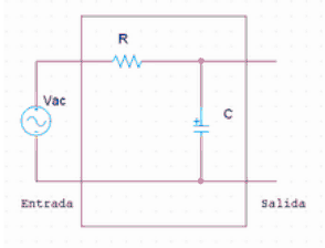
En este caso la fuente da 10V de tension de pico a una frecuencia de 50Hz, la resistencia es de [math]\displaystyle{ 3.3k\Omega }[/math] y el condensador vale [math]\displaystyle{ 1\mu F }[/math]
La impedancia total del circuito viene dada por la impedancia de la resistencia y la del condensador.
[math]\displaystyle{ Z_T=Z_R+Z_C }[/math]
[math]\displaystyle{ Z_R=3.3k\Omega \ _{0^\circ} }[/math]
[math]\displaystyle{ Z_C=\frac {1}{2\pi f C}_{-90^\circ}=\frac {1}{2\pi\cdot 50 \cdot 1\cdot10^{-6}}_{-90^\circ}=3183,09\Omega \ _{-90^\circ} }[/math]
[math]\displaystyle{ Z_T=Z_R+Z_C= 3300_{0^\circ}+3183.09_{-90^\circ} = \sqrt{3300^2+3183.09^2}_{tan^{-1} \frac{-3183.09}{3300}} = 4584.98_{-43.96^\circ}\Omega }[/math]
